
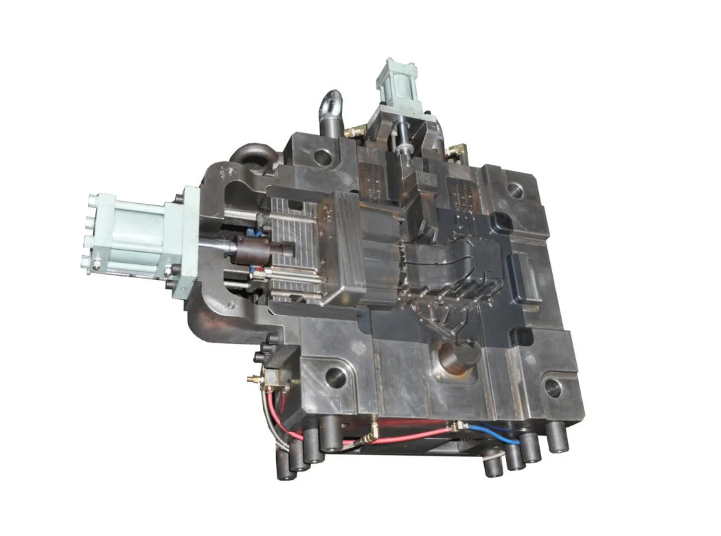
Die casting draft angle provides clearance as a casting releases from a die face or core. Specify it with the opening direction, feature depth and controlled dimension. A blanket angle can leave a pocket too small at its base or remove stock needed for a functional surface.
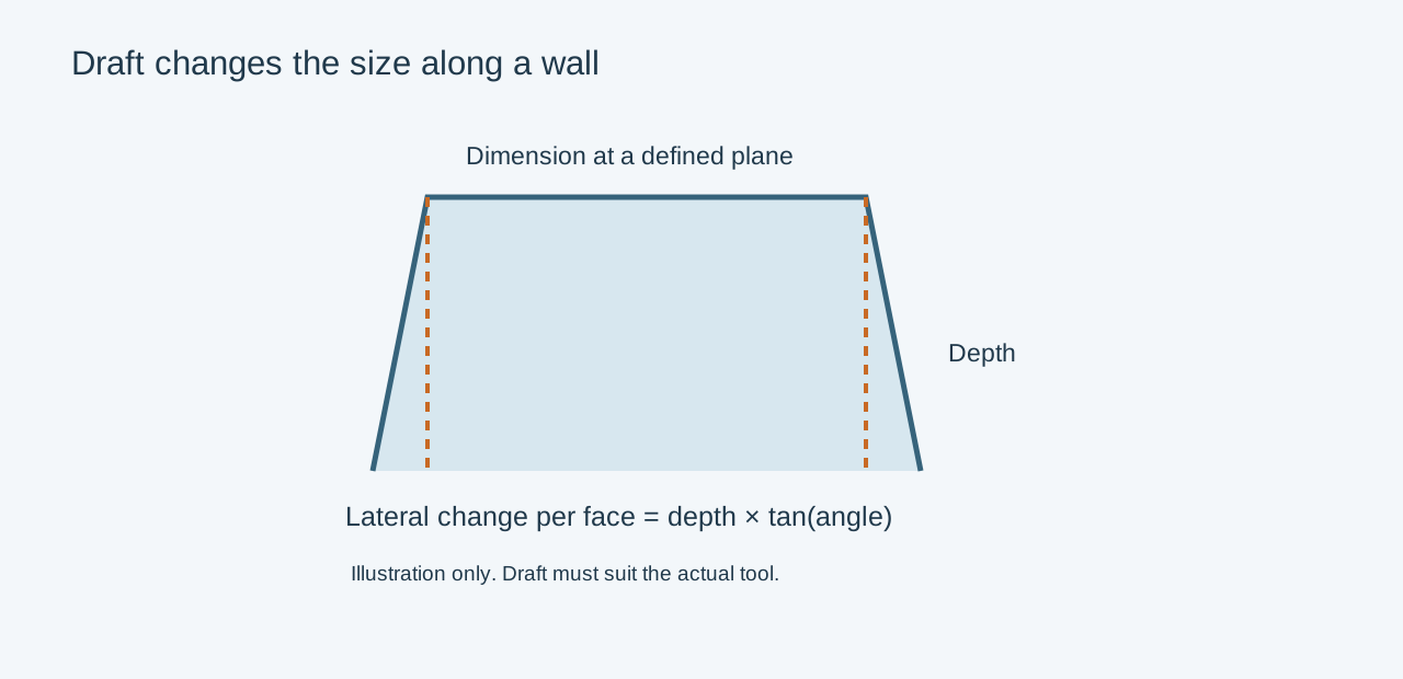
Establish how every feature releases
Mark the main die-opening direction first. Identify faces formed by the fixed half, moving half and any side actions. Internal walls tend to grip a core as the casting cools, so review them separately from external faces. Texture, wall depth and ejection support also affect the proposal.
A face that cannot clear in the main opening direction may need a slide, a geometry change or later machining. Removing draft in CAD does not resolve the release mechanism.
Dimension a drafted feature at a defined section
For a straight tapered face, the lateral change is depth × tan(angle). At an illustrative depth of 40 mm and angle of 1°, the change is approximately 0.70 mm per face. A symmetrical pocket changes about 1.40 mm across its width over that depth. These assumed values demonstrate dimensioning; they are not universal process recommendations.
| Drawing item | Specify | Why it matters |
|---|---|---|
| Pocket width | Width at a named depth or plane | Mouth and base widths differ |
| External wall | Datum and taper direction | Assembly clearance changes along the wall |
| Machined bore | Cast core and finished geometry | Draft must leave adequate local stock |
| Textured surface | Texture and permitted draft proposal | Surface texture affects release |
Keep functional exceptions visible
A connector may need a straight locating surface while the surrounding cavity can remain drafted. Machine only the functional region if that offers a practical tool path and fixture. Alternatively, change how the mating component locates. Compare the extra machining with the cost and maintenance of another die action.
For a deep enclosure pocket, check the actual PCB envelope at its installed height, including component clearance. Checking only the opening can miss interference lower in the housing.
Approve the draft model and sectioned drawing together before tool manufacture. Include the controlled dimension in the sample inspection plan. An angle on a drawing is useful only when the tooling team, inspector and assembly designer agree which section it controls.
Related engineering decisions
- Die Casting Parting Line Design: Where to Place It
- Machining Allowance on Die Castings: How to Specify It
- Related manufacturing service
- Read the broader engineering guide