
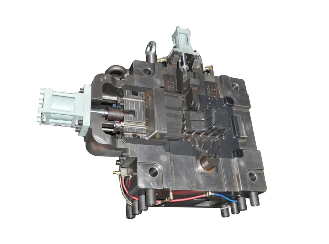
Flash in die casting is unwanted metal entering a gap between tool members. Its location and trend can help separate tool closure, wear, damage and process-related contributions. Removal is necessary in many routes, but trimming alone does not establish process control.
Map the flash before removing it
Record the cavity, parting edge, slide or ejector location. Compare thickness, extent and frequency under a consistent inspection method. Distinguish a sudden local change from a gradual increase across many runs.
| Observation | Check | Consequence to assess |
|---|---|---|
| Local new flash | Damage, contamination or closure interference | Edge integrity and tool condition |
| Increasing witness over time | Wear, alignment and maintenance history | Dimensional drift and trim burden |
| Pattern around a slide | Fit, lock and movement | Local mismatch and function |
| Broad process-linked change | Closure and casting operating window | Whether the tool system remains suitable |
Keep machine forces in context
Tool closure must be reviewed against the casting system, including projected area and relevant cavity pressure. The machine's nominal clamping-force rating alone is not a complete explanation. Avoid treating a higher setting as a substitute for checking damaged parting faces, alignment or tool support.
Changes to filling or pressure need a controlled review because they can affect other defects. Compare accepted output and tool condition after the change, not only the amount of flash on one sample.
Define the finished edge
A drawing should identify functional edges, permissible residual flash, burr conditions and cosmetic zones. Trim tooling, deburring and cleaning must reach the required areas without damaging seal lands, threads or thin walls. Check particles remaining in pockets and passages after removal.
For an illustrative connector enclosure, flash at a cable opening may interfere with the mating seal even when it is visually small. Define acceptance using the interface requirement and inspect after the complete edge-finishing route. A general instruction to “remove all burrs” does not specify the permitted edge break or protected dimensions.
Retain raw and finished samples during the investigation. Connect maintenance decisions to measured trends, then verify the corrected tool and production conditions before returning to routine inspection. This preserves evidence that would otherwise disappear during trimming.
Related engineering decisions
- Die Casting Parting Line Design: Where to Place It
- Cold Shuts in Die Casting: Causes and Corrective Actions
- Related manufacturing service
- Read the broader engineering guide