

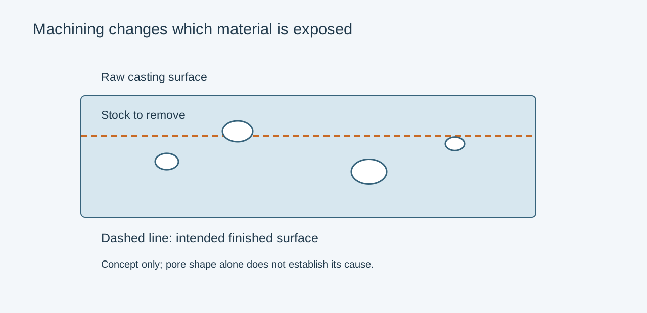
Machining can reveal porosity that was invisible on the outside of a die casting. Cutting changes which internal material becomes the final functional surface. The investigation should connect pore location, casting section and actual stock removal.
Record where the tool cut
Compare the raw casting, machining program and finished dimensions. Measure the stock distribution rather than assuming it matched the nominal model. Casting variation, fixture location and cleanup requirements can make one area lose more material than planned.
| Evidence | What it can explain | Useful comparison |
|---|---|---|
| Raw and final measurements | Actual stock removed | Good and affected parts |
| Identified cut section | Pore location relative to the surface | Equivalent cavity and location |
| Machining setup | Datum and clamp contribution | Setup or fixture changes |
| Finished leak result | Connected path under test conditions | Cleaned parts with known identity |
Distinguish exposure from creation
An exposed pore is not automatically proof that the machining operation created an internal void. It may have intersected a pre-existing discontinuity. Conversely, burrs, tearing or contaminated surfaces can complicate visual diagnosis. Clean the part appropriately and examine the actual surface before selecting corrective action.
Where relevant, compare suitable radiography, CT or sections with the machined feature. Agree the inspection's detection capability and acceptance zone. Do not infer leakage from every visible pore or dismiss leakage because the external surface looks clean.
Correct stock and local geometry together
Reducing unnecessary stock removal may help, but the finished feature must still clean up across casting variation. A smaller allowance that leaves incomplete machining is not an acceptable correction. Review core position, wall junctions, locating features and the casting process with the downstream route.
For an illustrative gasket flange, one corner needs excessive cleanup because the casting sits differently in the fixture. The trial should compare location repeatability and raw shape before changing the entire casting wall. If the underlying issue is a heavy local junction, the geometry and solidification strategy need attention too.
Qualify any repair or impregnation as a separate controlled route where permitted. Repeat the relevant dimensional and functional tests after the final cleaning and finish. Keep rejects identified by cavity, location and production interval so the next trial tests a specific explanation rather than a collection of unrelated process changes.
Related engineering decisions
- Machining Allowance on Die Castings: How to Specify It
- Leak Testing Die Cast Components: A Specification Guide
- Related manufacturing service
- Read the broader engineering guide