
The right aluminum die casting wall thickness depends on flow distance, alloy, geometry, die temperature and the required function. A single minimum thickness does not describe an entire housing. Review the main wall together with distant corners, rib roots, bosses and machined interfaces.
Map thickness through the component
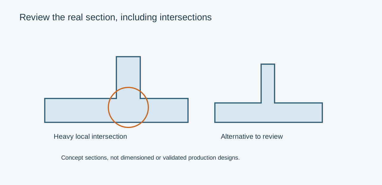
Start with sections through the longest flow paths and the largest changes in local mass. A nominally thin enclosure can still have a heavy screw-boss junction. That junction cools differently from the nearby wall and may become a local shrinkage concern. Making the whole enclosure thicker can increase weight without correcting that concentration.
Use smooth transitions and cored features where practical. The objective is a manufacturable distribution of material with enough stiffness and soundness for the application. Reducing every wall to the smallest possible value can introduce fill, handling and assembly problems.
| Location | Question for DFM | Trial evidence |
|---|---|---|
| Remote thin wall | Can metal reach the end before freezing? | Fill completeness at identified locations |
| Boss-to-wall junction | Is material accumulating locally? | Section or suitable internal inspection |
| Seal flange | Does the wall support machining and bolt load? | Flatness and finished leak test |
| Wide cover | Is stiffness sufficient after trimming? | Free-state and assembled measurements |
Include draft in the thickness review
A wall between two drafted faces does not necessarily retain a constant section. Identify the measurement plane and review the thick and thin ends. For an illustrative 30 mm wall depth, a one-degree taper on one face changes its position by about 30 × tan(1°) = 0.52 mm. Two faces can add or subtract their effects depending on direction. This is geometry, not a recommended casting allowance.
Validate the function after the final operation
A gasket flange may be thick enough to cast but too flexible when bolts compress the seal. A cover may pass its casting dimensions but distort after machining removes stock. Evaluate those states separately. Record cavity, sample condition and fixture restraint so measurements are comparable.
Send section views, the finished model and the critical load or sealing requirements for review. Agree any dimensional recommendation with the actual tool and process proposal. Use early samples to verify remote walls and heavy intersections rather than accepting only the easy-to-measure external envelope.
Related engineering decisions
- Die Casting Rib Design: Stiffness Without Excess Mass
- Screw Boss Design for Die Cast Components
- Related manufacturing service
- Read the broader engineering guide