
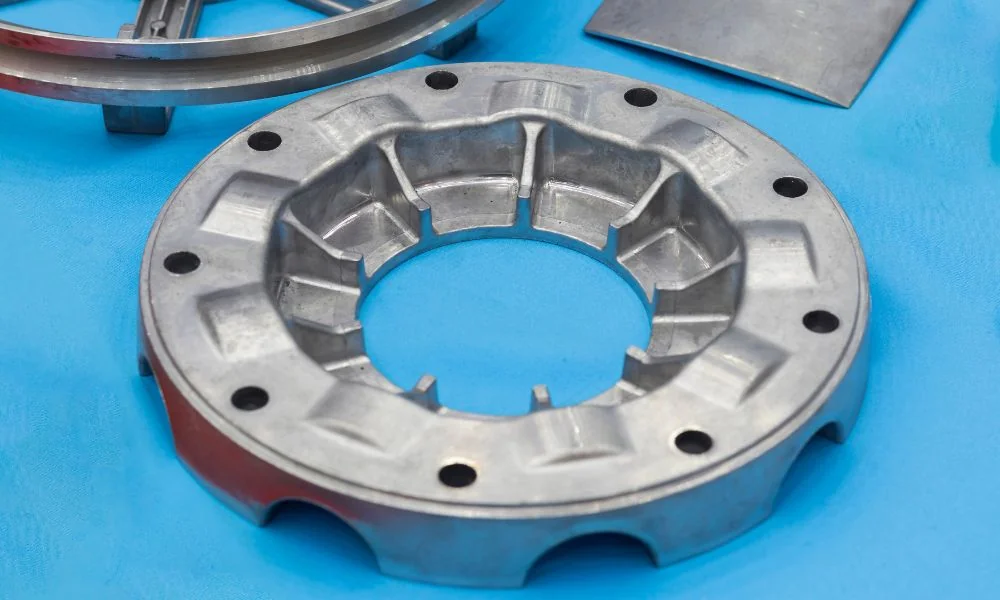
Die casting ribs can increase stiffness without turning an entire wall into a heavy section. Their geometry must still fill, release and avoid excessive material at intersections. Evaluate rib height, root, spacing and direction as a system.
Follow the load path
Place reinforcement where the assembly transfers load between mounting points, bearing supports or broad walls. A decorative rib that misses the load path adds weight without providing the intended benefit. Use structural analysis or an appropriate physical test to compare proposals.
Avoid interpreting a nominal rib-to-wall ratio as a universal design rule. Alloy, flow path, height, root fillets and the surrounding geometry change what is practical.
| Rib detail | Engineering question | Tooling question |
|---|---|---|
| Height | Does it improve the required stiffness? | Can the cavity fill and release? |
| Root | Is the transition sufficiently supported? | Does it create a heavy local junction? |
| Spacing | Is there access for cleaning or assembly? | Is the die steel practical and serviceable? |
| Direction | Does it carry the intended load? | Does it suit flow and die opening? |
| Boss connection | Is the fastener load distributed? | Does intersecting metal accumulate locally? |
Include draft and fillets in the real section
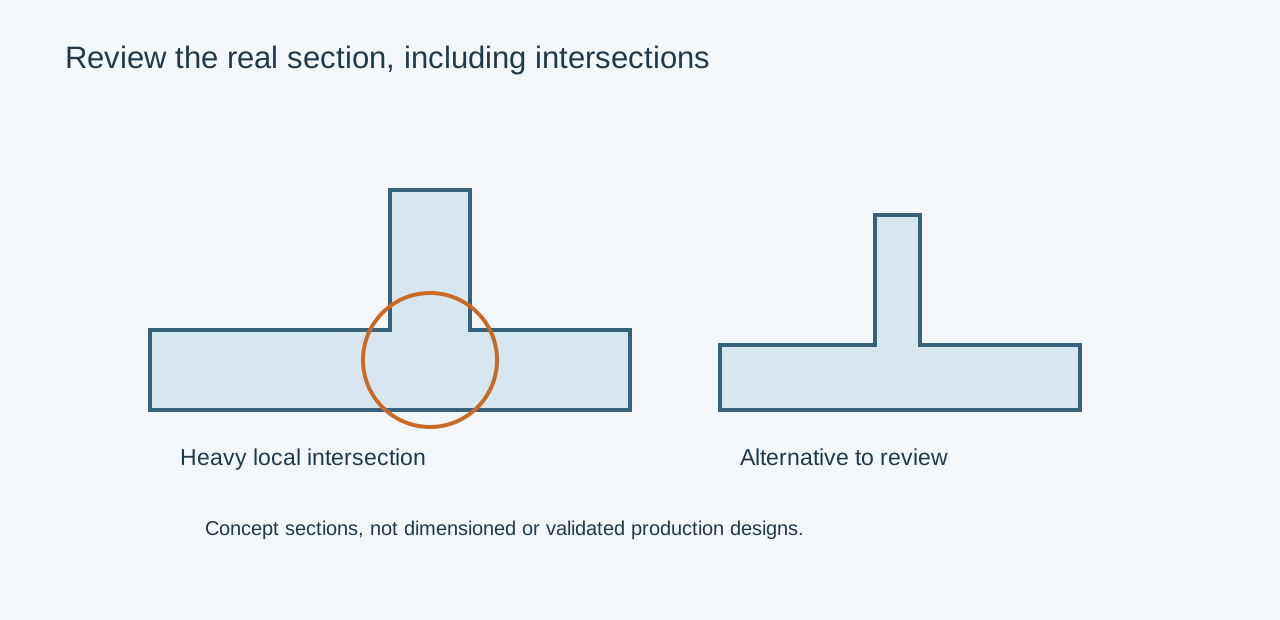
A tall rib that looks slender at its tip may become much thicker at the root once draft and fillets are added. Section the actual model. Multiple ribs meeting at a screw boss can create a concentrated mass even when each individual rib appears modest.
For an illustrative enclosure lid, compare two ribs running between mounting points with a uniformly thicker lid. Evaluate stiffness, mass, fill and distortion in both proposals. The useful result is the finished lid under its assembly load, not the highest possible rib count.
Verify more than the first filled sample
Inspect remote rib tips and deep roots on identified trial parts. Check ejection damage, local porosity where relevant and the finished assembly behavior. If the ribs guide air or support a gasket flange, test those functions in the installed orientation.
Keep boss thread engagement and fastener failure modes as a separate detailed review. A rib can support the boss externally while leaving insufficient material or soundness around the thread. Send the load case and mating geometry with the model so the casting and machining teams can assess the same requirement.
Related engineering decisions
- Aluminum Die Casting Wall Thickness: A Design Guide
- Screw Boss Design for Die Cast Components
- Related manufacturing service
- Read the broader engineering guide