

A surface profile tolerance controls a surface relative to its theoretically exact geometry under the specified drawing rules. For die cast parts, it can communicate a functional three-dimensional boundary more effectively than many unrelated point dimensions. The datum scheme and evaluation method remain essential.
State what surface and relationship are controlled
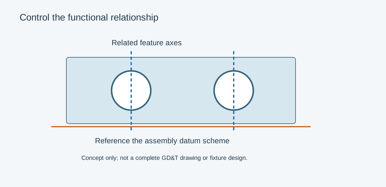
Identify the controlled region, nominal geometry, tolerance zone and applicable datum references. Clarify whether the requirement concerns shape alone or also orientation and location relative to the assembly. Use one governing drawing system consistently; ISO and ASME conventions should not be mixed casually.
| Drawing decision | Why it matters | Inspection question |
|---|---|---|
| Controlled region | Defines where the requirement applies | Which faces and boundaries are evaluated? |
| Nominal geometry | Establishes the intended surface | Which model revision is authoritative? |
| Datum reference | Constrains evaluation and assembly relation | How is the datum established? |
| Zone disposition | Determines permitted surface deviation | Is the zone arrangement unambiguous? |
| Part condition | Flexible castings can change shape | Free state or specified restraint? |
Avoid an unconstrained best fit
A scan compared with CAD can produce a visually impressive color map while allowing movement that the assembly datums do not permit. The alignment must reflect the specified requirement. Document the datum simulation, point or scanning strategy and treatment of inaccessible areas.
Discrete measurements also need adequate coverage. A few points can miss a local deviation between them. Choose the evaluation method around the controlled geometry and required decision, rather than selecting it solely because a CMM or scanner is available.
Match the callout to function
For an illustrative curved cover near a moving assembly, the requirement may protect a clearance envelope relative to mounting datums. A free best-fit profile might accept a cover whose shape is good but whose location interferes with the moving part. Define the relationship the product needs.
Review casting draft, parting witnesses and the final finish within that boundary. If selected pads are machined, specify their relationship without accidentally imposing an unnecessarily tight profile on every cosmetic surface.
Agree the drawing interpretation and measurement report format before tooling approval. An annotated example can prevent different teams from accepting the same casting under incompatible alignment rules.
Related engineering decisions
- Die Casting Tolerances: How to Specify Functional Requirements
- CNC Machining Tolerances: How Tight Is Worth the Cost?
- Related manufacturing service
- Read the broader engineering guide