

Die casting tolerances should distinguish raw casting dimensions from machined interfaces and finished assembly requirements. The useful tolerance is one that protects function and can be measured consistently on the specified production condition.
Classify the features before applying defaults
Separate dimensions formed within one die member from those crossing a parting line or involving a slide. Tool mismatch and movement can affect the latter differently. Identify flexible walls, deep cores, draft-dependent dimensions and machined surfaces. A single tolerance note does not explain these differences.
| Feature | Define on the drawing | Inspection consideration |
|---|---|---|
| General envelope | Casting tolerance basis and exclusions | Free state and measurement locations |
| Drafted pocket | Dimension plane and taper | Section or height of measurement |
| Bearing seat | Finished size, form and datum relation | Machined and final-finish condition |
| Gasket land | Functional geometry and permitted restraint | Clamp condition and assembly state |
| Parting witness | Step or flash limits where relevant | Distinguish metal from removable flash |
Name the applicable standard precisely
ISO 8062-3:2023 addresses general casting tolerances and machining allowances within its scope. Its existence does not establish that a particular supplier can achieve every grade on every feature. Other drawing systems and customer-specific requirements may apply. Resolve the governing system, edition, individual exceptions and inspection method with the manufacturing proposal.
Do not reproduce a tolerance chart without its size range, feature type and conditions. A value taken out of context can become an unintended guarantee.
Allocate precision where it changes the assembly
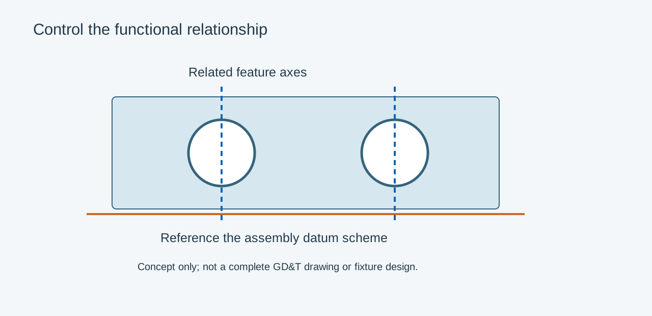
Consider a housing with a mounting flange and a bearing bore. The bore size alone cannot ensure shaft alignment; the relationship between the bore axis and mounting datum may control the assembly. Conversely, a nonfunctional outer rib may not need the same tight dimensional limit. Build the datum scheme around how the housing is located and loaded.
Review the cumulative stack using the actual mating parts. Reserve machining for the interfaces that need it, and ensure casting variation still leaves enough stock for cleanup. Check coating effects when the delivered dimensions include a finish.
During trials, compare results by cavity and condition. Use an agreed measurement setup and adequate measurement capability before interpreting process variation. An attractive first-article report is a starting point; repeat production needs a control plan for the critical features.
Related engineering decisions
- Surface Profile Tolerances for Die Cast Parts
- Bearing Fit Tolerances in Aluminum Motor Housings
- Related manufacturing service
- Read the broader engineering guide