

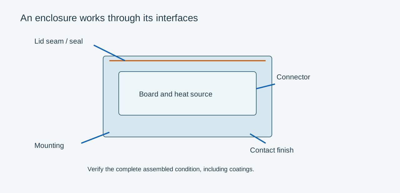
Optical transceiver housing design connects thermal contact, electromagnetic shielding, mechanical retention and host-interface dimensions. A small casting may contain several tightly interacting surfaces, so the manufacturing plan should identify which interfaces are functional and how they are verified.
Start from the actual module interface
Use the applicable module form-factor and host-interface documents for the product. Identify the controlled external envelope, connector relationship, latch movement and insertion clearance. Do not derive production dimensions from a photograph of a familiar module.
| Interface | Design question | Manufacturing review |
|---|---|---|
| Host engagement | What controls insertion and retention? | Datum scheme and finished envelope |
| Thermal contact | Where does heat cross the housing boundary? | Contact geometry, finish and clamp condition |
| Shielding seam | How is current continuity maintained? | Joint geometry and conductive contacts |
| Internal board | What locates the electronics? | Boss, pocket and assembly clearances |
| Optical region | What cleanliness and alignment are required? | Edge finishing and handling route |
Avoid using casting detail as a substitute for interface control
Draft, parting witnesses and coating build can affect a small mating envelope. Place the controlled dimension at a defined section and identify any post-cast machining. Thin walls and local bosses need a filling and ejection review rather than a blanket minimum-wall promise.
For a thermal-contact pad, agree the final geometry, roughness where necessary and surface treatment. A high-conductivity material claim alone does not establish module temperature. Include the actual heat source, interface material and host cooling condition in thermal validation.
Qualify the finished assembly
A conductive housing still needs suitable seam, connector and contact design for shielding. Coatings that protect the exterior can interfere with electrical or thermal interfaces unless boundaries are controlled. Define deburring and cleanliness for the electronic and optical assembly route.
An illustrative revision that adds a latch relief may improve insertion but weaken a local wall or create an awkward die action. Review host function and casting feasibility together before changing tooling.
This article describes design decisions, not a claim of a particular qualified module platform. Submit the governing interface drawing, thermal conditions, finish map and inspection requirements with the RFQ. Keep module compliance and production validation attached to the exact assembled configuration.
Related engineering decisions
- EMI Shielding Design for Die Cast Enclosures
- Die Cast Heat Sink Design: From Heat Load to Geometry
- Related manufacturing service
- Read the broader engineering guide