

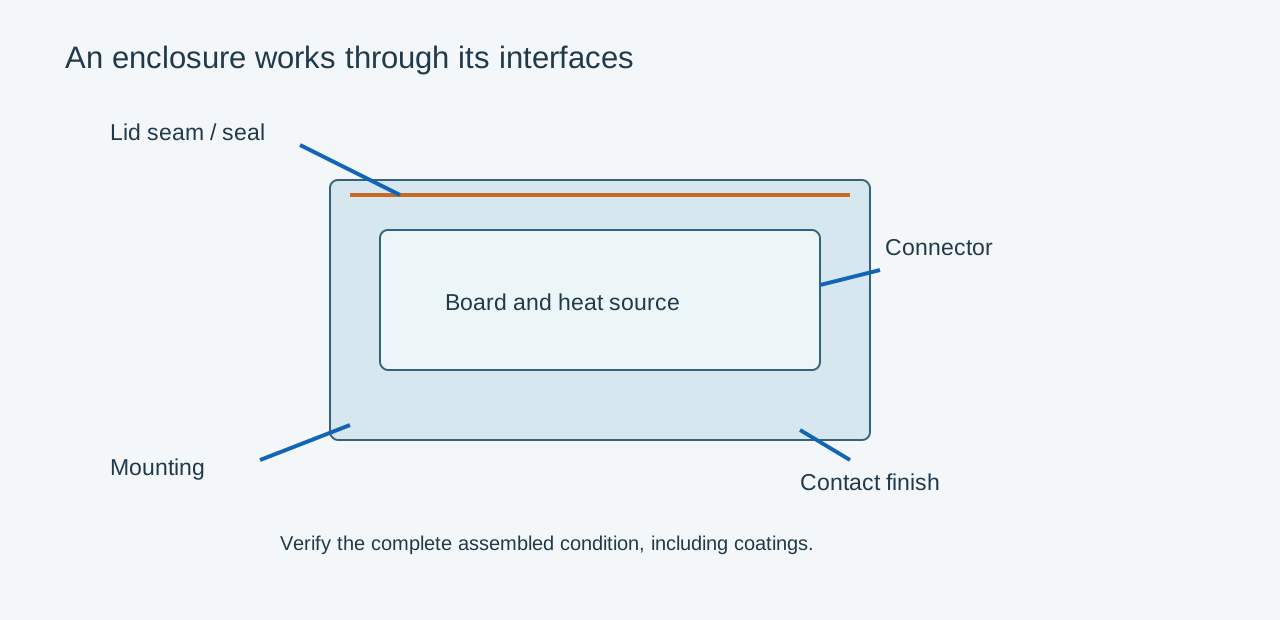
EMI shielding in a die cast enclosure depends on the complete conductive boundary. Seams, apertures, connectors and contact finishes can dominate the result. Increasing wall thickness alone may do little if a poorly connected lid provides a leakage path.
Define the shielding requirement
State the relevant frequency range, test arrangement and required system result. Separate enclosure shielding evaluation from the product's complete electromagnetic-compatibility requirements. A generic decibel figure without its test method and frequency range is not a useful acceptance criterion.
| Boundary feature | Review | Manufacturing implication |
|---|---|---|
| Lid seam | Continuous contact or qualified gasket | Land geometry and fastener support |
| Connector opening | Shield termination and aperture | Controlled cutout and mating interface |
| Vent | Required airflow and electromagnetic path | Qualified vent solution |
| Contact finish | Conductivity, compatibility and durability | Masking and surface preparation |
| Fasteners | Joint pressure and repeat assembly | Boss strength and seating condition |
Treat the gasket as an engineered interface
An EMI gasket needs the specified compression and electrical contact along the joint. Flatness, fastener spacing and enclosure stiffness influence local contact. The material combination also needs an environmental review: a conductive filler and aluminum substrate can create galvanic-corrosion concerns in the presence of an electrolyte.
A waterproof gasket is not automatically a conductive gasket, and an EMI gasket does not automatically provide the required environmental seal. Where both are needed, qualify the complete joint arrangement.
Keep coatings and apertures in the test article
For an illustrative controller, a powder-coated lid may leave an electrically insulating seam unless the design provides a suitable contact route. Define masking or a qualified conductive finish at the interface. Avoid depending on random scratches from tightening to establish repeatable continuity.
Test the production-intent lid, connectors, cables, vents and fasteners over the required operating range. Include relevant disassembly or environmental conditioning if it changes the contact system. A prototype with taped seams or omitted connectors may diagnose a problem, but it is not equivalent to the delivered configuration.
Provide the interface requirements and coating map before tooling release. This lets the casting, machining and finishing teams preserve the surfaces on which the shielding design depends.
Related engineering decisions
- Die Cast Enclosure Design: A Practical Engineering Guide
- Die Casting Design for Optical Transceiver Housings
- Related manufacturing service
- Read the broader engineering guide