

Die cast heat sink design starts with heat load, allowable temperature and cooling conditions. Fins are useful only when heat reaches them and air can remove it. A compact casting with many closely spaced fins can perform worse than a more open geometry in the actual installation.
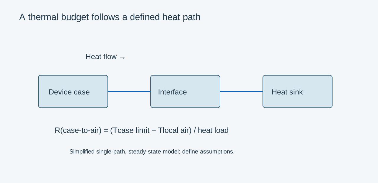
Build the thermal budget first
Identify where the temperature limit applies: semiconductor junction, device case, circuit board or another measured surface. Use local cooling-air temperature rather than an unrelated room value. Include interface resistance and the relevant heat path. Device package metrics measured under one test arrangement should not be treated as interchangeable physical resistances.
For a simplified steady-state example, assume all 30 W passes from a device case through one interface into the sink. A case limit of 80°C and local air at 40°C allow (80 − 40) / 30 = 1.33°C/W from case to air. If the interface consumes an estimated 0.20°C/W, approximately 1.13°C/W remains for sink to air. These assumptions are illustrative, not a rating for a ZAODA component.
Connect the budget to geometry
| Design item | Review | Evidence |
|---|---|---|
| Contact pad | Flatness, roughness and clamp pressure | Interface assembly trial |
| Base | Heat spreading and local thickness | Analysis and temperature measurements |
| Fins | Fill, draft, spacing and airflow access | DFM plus thermal validation |
| Mounting | Fastener load and installed orientation | Test in representative installation |
| Finish | Contact masking and surface condition | Finished assembly test |
Use the conductivity of the proposed casting alloy and condition. A value for pure aluminum or an extrusion grade does not establish the behavior of a die-cast housing. Thicker bases may improve spreading in one design while increasing mass and casting difficulty in another.
Validate the installed cooling path
Keep fins aligned with the intended airflow where practical. Natural convection depends on orientation and available air movement; forced convection depends on the fan and system resistance. Include adjacent walls, cables, covers and recirculated warm air in the test arrangement.
Before tooling release, identify which thermal contact faces will be machined and which will be masked during coating. Test production-intent castings with the actual interface material, clamp arrangement and heat source. A fin photograph or an isolated material conductivity value cannot establish a continuous power rating.
Related engineering decisions
- Die Cast vs Extruded Heat Sinks: How to Choose
- Die Casting Design for LED Light Housings
- Related manufacturing service
- Read the broader engineering guide