

An aluminum motor housing connects the stator, bearings, mounting structure and cooling environment. Design its manufacturing route around the motor's alignment and operating conditions rather than treating the housing as a cylindrical casting with a few holes.
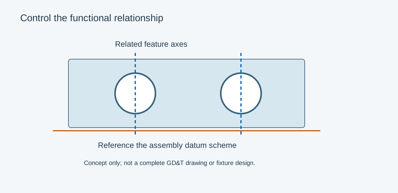
Define the functional datum chain
Identify the bearing axes, stator location, mounting flange and end-cover interfaces. Decide which relationships require machining in a common setup. A tight bore diameter does not by itself control the bore axis relative to the motor mounting surface.
| Function | Drawing information | Validation condition |
|---|---|---|
| Bearing support | Size, form, shoulder and datum relationship | Machined and assembled housing |
| Stator location | Fit basis, temperature and installation method | Production-intent assembly |
| Mounting | Flange geometry and fastener load | Installed restraint |
| Cooling | Heat source, fins or channel requirements | Representative thermal operation |
| End sealing | Seal land, groove and finish | Complete finished joint |
Review thermal fits explicitly
Aluminum housings and steel bearing rings expand differently. Their temperatures can also differ during operation. Fit selection must consider load direction, housing stiffness, required axial movement and the bearing supplier's recommendations. A generic H7 callout should not become the default for every motor arrangement.
Keep bearing retention and internal clearance in the same review. Increasing interference can improve retention while changing ring deformation and clearance. Confirm the selected arrangement over the intended temperature range.
Preserve a sound machining envelope
Core the housing to support a practical cast section and machining allowance. Heavy bearing bosses and thin adjacent walls need a local solidification review. Plan fixture supports so clamping does not create an apparently round bore that changes shape after release.
For example, a flanged motor shell may be inspected free-standing but run bolted to a rigid frame. Compare the bore geometry in both agreed conditions if assembly restraint materially changes it. Keep tightening sequence and fastener load documented.
Prototype machining can establish assembly access and datum logic. Cast samples must still establish fill, soundness and the finished route. Provide the motor assembly, operating temperatures, load case and bearing arrangement with the RFQ; do not rely on the housing model alone to communicate those requirements.
Related engineering decisions
- Bearing Fit Tolerances in Aluminum Motor Housings
- Fixture Design for Machining Die Cast Components
- Related manufacturing service
- Read the broader engineering guide