
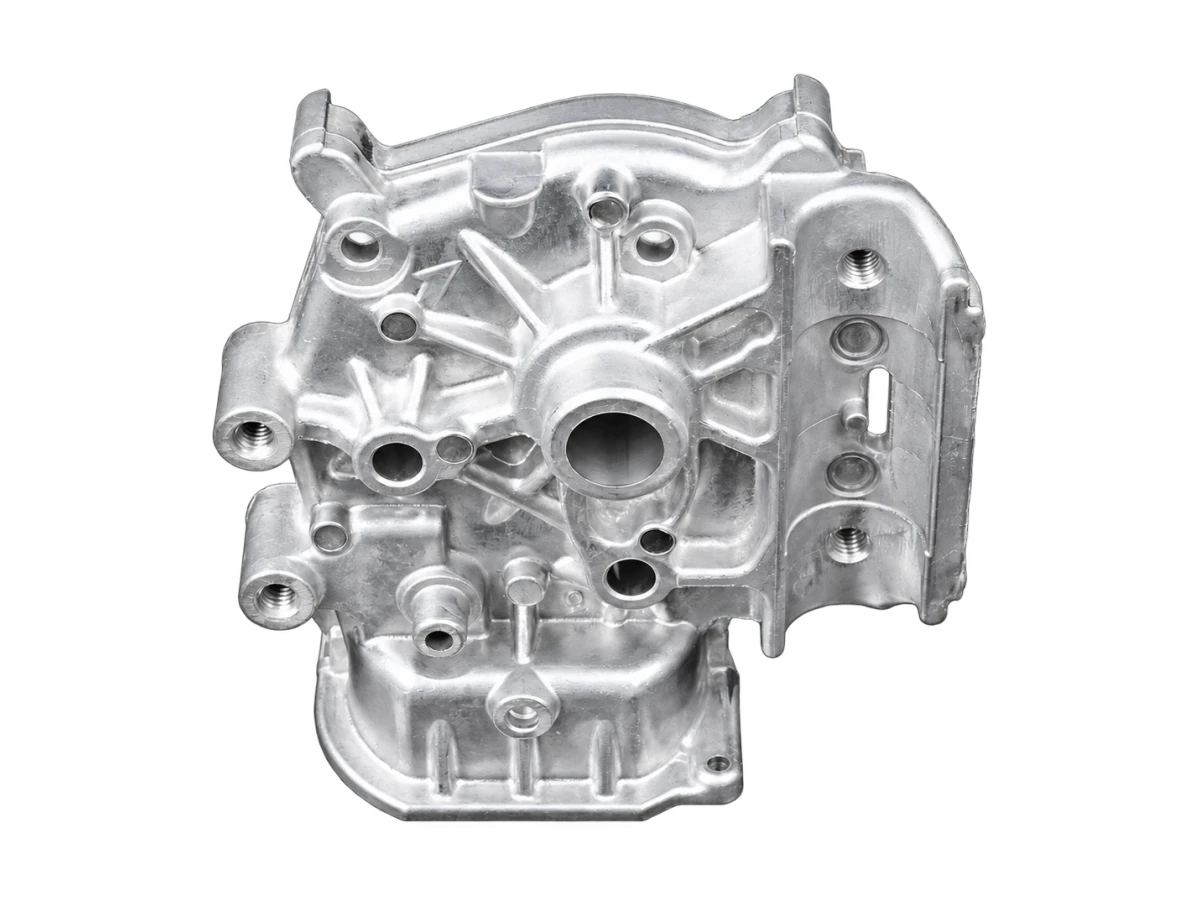
Cast the body and machine the functional interfaces
An aluminum motor housing can combine a cylindrical body, cooling ribs, mounting feet and connection features. End covers and flanges complete the mechanical interfaces around the motor assembly. Die casting is a route to review when repeat demand and stable geometry can justify dedicated tooling.
Define whether the quotation covers a bare housing, an end cover, a machined component or a specified subassembly. Motor windings, rotor design and electrical performance remain separate requirements unless they are explicitly included in the project scope.
Make bearing and mounting relationships explicit
Bearing seats, pilot diameters and flange faces often determine how the motor assembles. The drawing should identify datum features, fits, surface requirements and geometric relationships. A diameter tolerance by itself does not describe alignment between two bearing locations or their relationship to a mounting face.
Plan machining setups around the functional datum system. Review fixture access, clamping distortion and the sequence for bores and faces. Where opposed bores require a controlled relationship, the process plan needs to show how that relationship will be established and measured.
Review ribs, wall sections and casting access
Cooling ribs and mounting bosses must suit both the motor envelope and the casting tool. Deep ribs, abrupt thickness changes and inaccessible undercuts can complicate fill, ejection or trimming. The DFM discussion should identify which features can remain as cast and which need machining stock.
Temperature, vibration and mounting loads should be supplied as design inputs. Material and manufacturing review do not replace validation of the motor assembly. Where leak testing or pressure containment matters, state the medium, pressure, allowable leakage and test stage.
Inspect and handle the finished housing as a precision part
Agree inspection for bearing seats, flange geometry, bolt locations and threads. Surface finish and coating allowances belong on the drawing, with masking around fits and electrical contacts. Protect machined bores and mounting faces during packing so that handling damage does not prevent assembly.