

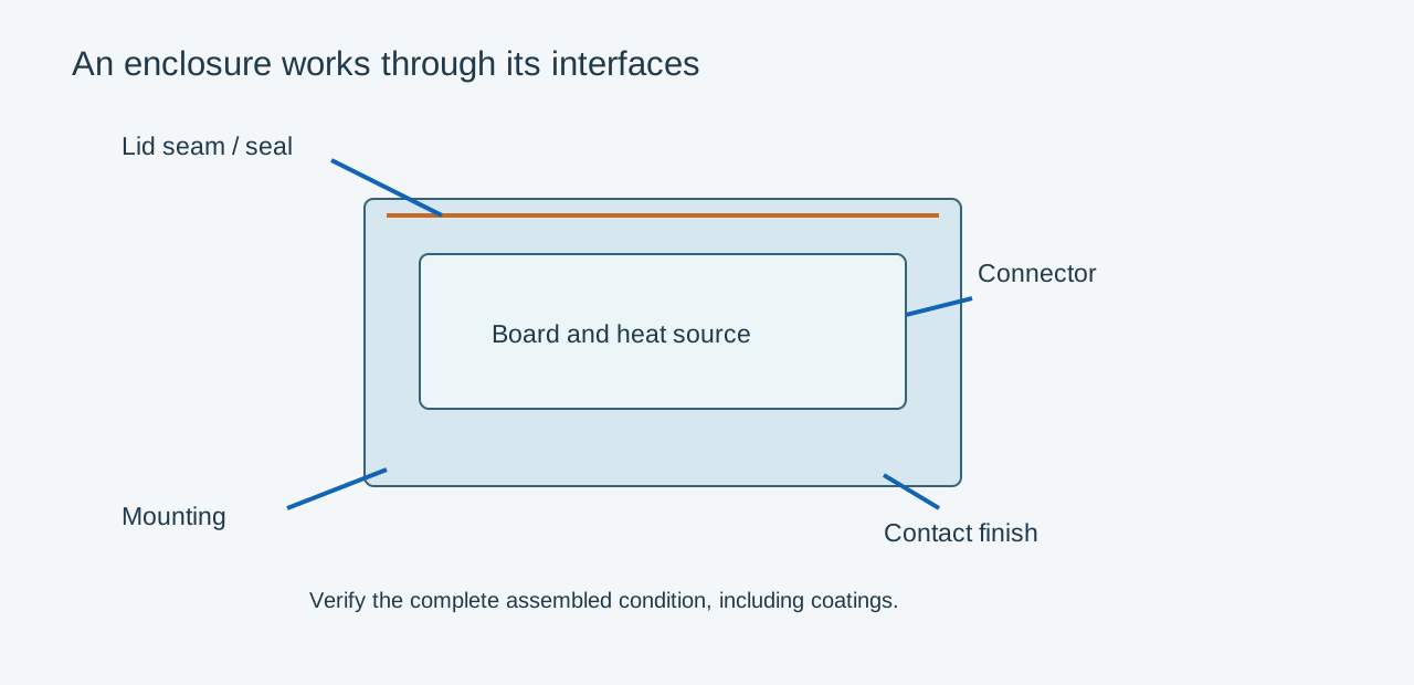
Die cast enclosure design must resolve the board envelope, connector access, lid joint, mounting and thermal path together. A housing that casts cleanly can still fail because a screw is inaccessible or the PCB collides with a drafted wall.
Start with an assembly envelope
Place the PCB, tall components, cables and mating connectors in the model. Include assembly motion and tool access. Review pocket clearance at the installed board height, not just at the opening. Keep casting draft, coating build and dimensional variation in the clearance model.
| Interface | Design decision | Verification |
|---|---|---|
| PCB supports | Location, screw access and electrical clearance | Assembly model and physical trial |
| Connector openings | Position, orientation and mating access | Mating connector or assembly gauge |
| Lid joint | Seal geometry, stops and fastener load | Finished joint and leak test if required |
| Mounting feet | Load path and datum scheme | Installed load and dimensional checks |
| Grounding | Conductive contact and coating boundaries | Defined electrical measurement |
Make sealing a joint design task
Specify gasket material, groove geometry, compression target and how tightening is controlled. The gasket supplier's data and the complete tolerance stack should guide the design. Define whether a coating lies under the seal and how contact marks or parting witnesses are controlled.
An IP classification applies to the tested enclosure assembly and defined conditions. A metal box, an isolated casting leak test or a gasket drawing alone does not establish that classification. Include connectors, cable entries, fasteners and the final lid in the relevant validation.
Assign machining to functional surfaces
Machine seal lands, locating bores or connector seats where function requires it. Leave adequate stock while avoiding unnecessary removal into internal discontinuities. Establish casting datums that the machining fixture can locate consistently. Keep ejector marks and trimming witnesses outside sensitive seal or cosmetic zones where feasible.
For an illustrative control enclosure, moving a PCB screw boss away from a connector improves driver access but may thicken the nearby wall junction. Review both assembly and local casting sections before approving the change.
Send the assembly model and a marked interface drawing for quotation. State environmental exposure, thermal load, critical dimensions, appearance zones and annual order cadence. Those inputs support a coherent manufacturing route instead of separate, conflicting assumptions for casting, machining and finishing.
Related engineering decisions
- EMI Shielding Design for Die Cast Enclosures
- Leak Testing Die Cast Components: A Specification Guide
- Related manufacturing service
- Read the broader engineering guide