Electronics and controls

Die Cast Electronic Enclosures

Custom die cast enclosures for electronics and controls, with PCB mounts, connector openings, sealing faces and finish masking defined around your assembly.

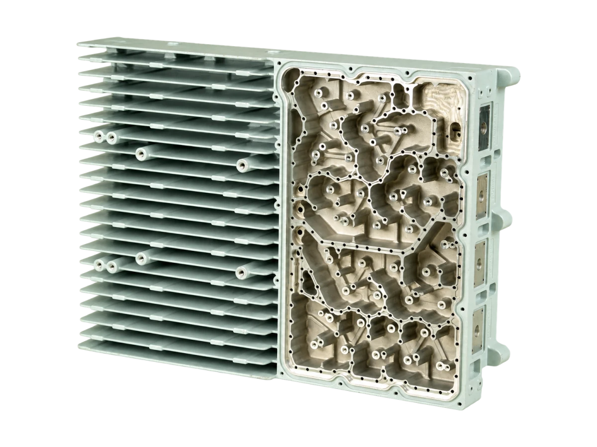
Finned electronic enclosure with internal ribs, mounting bosses and connector openings
Component requirements

Product specifications for your RFQ

These are configuration and review inputs. Final dimensions, material, finish and acceptance criteria follow the agreed drawing.

Product forms
Control boxes, communication housings, covers and chassis
Material route
Aluminum or zinc alloy reviewed against size and function
Internal features
PCB standoffs, ribs, connector locations and cable clearances
Machined features
Gasket lands, threaded holes and precision mating interfaces
Finish planning
Cosmetic surfaces, grounding contacts and masking zones
Inspection focus
PCB datums, cover fit, connector position and sealing geometry
Design & Application Guide

Build the enclosure around the electronic assembly

A die cast electronic enclosure combines protection, mounting and assembly features in a metal body. Typical configurations include controller boxes, communication equipment housings, sensor covers and industrial electronic chassis. Internal ribs and bosses can support a PCB or connector while the outer body provides mounting and handling surfaces.

Start with the PCB envelope, component heights, connector drawings and assembly sequence. Clearance must account for the real board, fasteners, cabling and access for tools. Moving one boss can change both the tool design and the way the electronics are assembled.

Choose material and geometry as a complete route

Aluminum and zinc alloys should be compared against size, mass, detail, service temperature, finish and expected demand. The enclosure should not inherit a material choice solely because a similar-looking product uses it. Confirm the alloy designation and the required material documentation.

Review wall transitions, rib roots, draft and ejection with the part geometry. Locate parting lines and cosmetic restrictions early. Connector openings or precision slots may need secondary machining, particularly where their positions are controlled from PCB mounting datums.

Define sealing and electrical contact zones

Cover flatness, gasket compression and screw spacing influence assembly fit. Identify mating surfaces and show the datum relationship between the body, lid and connectors. Where sealing is required, specify the test conditions and whether testing applies to a component or the complete enclosure.

A conductive metal body can form part of an EMI shielding design, but shielding performance also depends on joints, apertures, gaskets and contact continuity. Coating and anodizing can change electrical contact behavior. Mark grounding lands and masking zones rather than assuming a decorative finish provides the required connection.

Inspect the interfaces that control assembly

A useful inspection plan covers PCB mounting locations, connector positions, cover fit, threads and gasket geometry. Define cosmetic zones and a reference sample for visible surfaces. If cleanliness, ingress testing or electrical continuity checks are required, agree the method, sampling and acceptance criteria before production release.

Manufacturing Route

From your drawing to an agreed component route

  1. 01

    Review the electronic envelope

    Confirm PCB, connectors, cable access and cover arrangement.

  2. 02

    Develop the casting and datum plan

    Resolve ribs, bosses, draft and mating surfaces.

  3. 03

    Machine and finish the interfaces

    Control openings, gasket lands and electrical masking.

  4. 04

    Check fit and agreed acceptance

    Inspect mounting geometry, cover fit and cosmetic zones.

Product FAQ

Questions before you quote

Can an enclosure include cast PCB standoffs?

Standoffs and ribs can be included in the casting review. Their locations, fastening method, draft and access must suit both the die and the electronic assembly.

Does a metal enclosure guarantee EMI performance?

No. Joints, apertures, contact resistance, shielding gaskets and the finished assembly determine performance. Provide the required test conditions.

Should connector holes be cast or machined?

The decision depends on their shape, tolerances and relationship to mounting datums. Quote the final functional requirements so both routes can be assessed.

Ready for a manufacturing review?

Request a Quote

Submit drawings, 3D models and specifications for review. Include material, quantity, tolerances and finish requirements.

Request a Component Quote →

Necessary storage supports secure forms, website sessions and your privacy choice. Optional analytics helps ZAODA understand visits, page use and enquiry interactions. Website Analytics is enabled by default. Uncheck it and save your preferences to stop analytics.

Your choice is saved for 180 days. We ask again when it expires or these settings change.

Necessary

Always active

These cookies keep the website and enquiry forms working securely and remember your privacy choice. They also support administrator authentication.

Cookies and browser storage

Necessary: zaoda-session and XSRF-TOKEN cookies support sessions and form security and last for 2 hours, renewed by website activity. The zaoda:consent local storage record remembers this privacy choice until its expiry. Optional analytics: zaoda:analytics:visitor uses local storage; zaoda:analytics:session and zaoda:analytics:last-activity use session storage. A new analytics session begins after 30 minutes of inactivity. These identifiers are removed when analytics is declined, consent expires or the consent version changes. Session storage normally ends with the browser tab; browser settings can also clear site data.

Cookie Policy
Upload Drawings · Request a Quote ↗